Ethernet Splitter
An Ethernet splitter can split a single Internet connection so that two or more computers can connect to the Internet simultaneously. It can also create additional connections for other computers on a network, which can reduce the overall amount of cabling required to setup a network. Unfortunately, Ethernet splitters cannot resolve the network collision issues that may occur if the computers connected to the splitter are using the same network resources simultaneously.
The CAT 5E Ethernet splitter allows two separate devices to share the same Ethernet cable. Ethernet splitters are generally used in pairs, with one CAT 5E splitter at the outlet and another Ethernet splitter at the patch panel. This allows for several wiring configurations to connect more devices to your network. Primus Cable offers both Ethernet splitter adapters and pigtail type Ethernet splitters.
Our phone cable is commonly used for 10Base-T and 100Base-T networking, particularly for telephone and low speed data applications. We stock both phone cable for plenum and for riser applications. If your project involves installation in plenums or air spaces, the CAT 3 Bulk Cable, Plenum CMP Solid UTP 25Pair 24AWG, 1000, White is a wise choice.
This phone cable features 25 unshielded solid copper pairs in a 24 AWG diameter cable. This phone cable is ideal for indoor voice communications applications, and is supplied on a wooden spool. This CAT 3 phone cable is also easy to install with its color striped pairs.
Primus Cable provides a wide assortment of networking and telco tools for your installation project. EZ-RJPRO™ HD Ratchet Crimp Tool is the professionals’ choice when working with CAT 5E and CAT 6 RJ45 connectors. It also works well with EZ-RJ12/RJ11 connectors. This crimping tool functions as a wire cutter, stripper, and crimping tool all in one. The ratcheted straight action crimping motion ensures a uniform crimp every cycle. Features precision cast crimping dies for superior accuracy.
How to Connect an Ethernet Splitter
Step 1 – Insert one end of the Ethernet splitter into the primary Ethernet port of the device that is providing the network connection (such as the cable/DSL modem or Internet router).
Step 2 – Insert the Ethernet cables from the devices to be connected (such as a computer, printer, or scanner) into the Ethernet splitter. Users often connect a printer and computer to the splitter in order to minimize the frequency with which network collisions occur while sharing the connection.
Step 3 – Test the connection of the devices on the splitter to ensure that they can connect to network resources.
How to Make an Ethernet Splitter
Step 1 – Procure the following materials: a short Ethernet cable, 2 x RJ45 keystone jacks, electrical tape, super glue, and crimp tool.
Step 2 – Crimp one end of the Ethernet cable so that the wire’s ends are visible. Leave the other end of the cable in-tact.
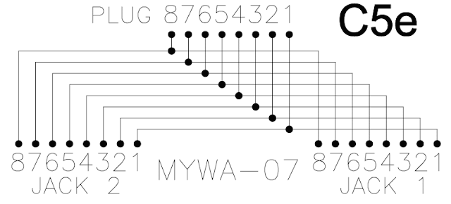
Step 3 – Follow the directions that come with the keystone jacks to open them, then place the wires from the Ethernet cable into the jacks to split the connection. Place the white and orange wires into Pin #1, the orange wire into Pin #2, the white and green wires into Pin #3, and the green wire into Pin #6. On the second keystone jack, place the white and blue wires into Pin #1, the blue wire into Pin #2, the white and brown wires into Pin #3, and the brown wire into Pin #6.
Step 4 – Glue the jacks to each other by the sides with super glue, then snap them together.
Step 5 – Wrap electrical tape around any exposed wires and begin using the new Ethernet splitter.
This diagram works in a half duplex mode which provides communication in both directions, but only one direction at a time. Under normal operation, each port is constantly sensing any traffic through its receiving pair of wire. As long as it can sense that data is being processed, it will not start sending data. The significance of this operation is to avoid collision where two ports are sending data at the same time, and due to this phenomenon, data will be discarded. When this issue is resolved by both computers, they will start to transmit at random amount of time. The circuit employs the method known as Carrier Sense Multiple Access / Collision Detecion (CSMA/CD) wherein it allows the devices to take turns using the signal carrier line. In this operation, the hub’s primary task is to allow each port to check the signal level of the line to determine whether someone is already using it. The device waits for a few seconds if it is in use, or it transmits otherwise.


No comments:
Post a Comment